Classification by Type/Function
No two ovens or kilns were alike, but all of them were very inefficient, highly polluting and dangerous to health.

No two bottle ovens or kilns were the same, but they all created vast volumes of smoke when they were baited (stoked). Almost all of them were built without any architect's drawings. They were built 'by eye' based on the experience of the local builder and the requirements of the factory owner. Specialist bottle oven builders were known to build an oven, from scratch, in 6 weeks.
Ovens and kilns all had very different 'characters'. Their firemen (the men responsible for firing the oven) had to learn how best to work with them. They had to control and cajole the way they performed and fired.
But all these ovens and kilns had one distinct and common feature, their bottle-shaped chimney. It could be round or square at its base, with either a bulbous and rather sinuous chimney, or a straight sided cone shaped chimney.
 |
| Burslem Acme Marls, Bournes Bank, 1960 |
All potters' bottle ovens and kilns were described as intermittent since the firing process occurred periodically. The oven was filled (placed) with pottery, then fired to temperatures which could be as high as 1450ºC, for some pottery recipes, then cooled and emptied (drawn). Then the process would start all over again.
Busy factories aimed to fire their ovens on a weekly basis; placing, firing and drawing on the same days. Large or high temperature ovens took much longer.
Of the 2000 or so coal-fired bottle ovens and kilns which once littered the skyline of the Potteries only 47 remain standing complete with their chimney today (2023). Three more exist in a collapsed state.
Using and firing them is no longer permitted, the Clean Air Act of 1956 out a stop to their use and signalled their decline. They were replaced in the 1960s with modern kilns using alternative fuels such as electricity, gas and oil. (Interestingly, the use of coal in the UK has 'fallen off a cliff' since 2012. And since 1990 the UK has cut its carbon emissions by around 40%)
What's the difference between a bottle oven and a bottle kiln?
The terms, bottle oven and bottle kiln, are often used interchangeably. The word kiln is mostly used generically. To most of us ovens and kilns mean the same thing - a complex brick-built, bottle-shaped structure for the firing of pottery or associated materials.Most of us assume them to be the same and to do the same job. However, although both bottle ovens and bottle kilns have that bottle-shaped chimney, and both types were fired with coal, there are technical differences between them. And as with all the terms used in the Staffordshire Potteries their usage varied from factory to factory and from town to town. It is difficult to be precise.
BOTTLE OVEN
Within the industry, the term bottle oven meant the potter's biscuit or glost oven which was fired with coal producing long flames that passed from the firemouths directly into the firing chamber to envelop its contents. The pottery inside the chamber needed to be protected from the flames, gases, smoke, sulphur fumes, ashes and dust (the products of combustion) in fireclay boxes called saggars.
Bottle ovens were either updraught or downdraught.
BOTTLE KILN
A bottle kiln was completely different from an bottle oven, and there are two types.
These kilns were used for the firing of 'heavy clays' (bricks, tiles, drainpipes, chimney pots and sometimes large pottery) and 'domestic ware' (salt glazed or dipped pottery). They were not bottle shaped at all but were described as 'downdraught beehive kilns'. They were characterised by their separate tall chimney. These were found in great numbers in the Potteries, but all of them have been demolished. They were also found in other parts of the UK but just a few now remain.
SIMPLE (or BASIC) UPDRAUGHT BEEHIVE KILN
The simple or basic updraught beehive kiln has a short conical
chimney built on top of the kiln. The kiln was sometimes built inside one of the buildings of the factory, the short chimney poking through the roof. A good example of this can be seen (April 2020) at the Wetheriggs Pottery in Cumbria. Sometimes they were free standing.
FRIT KILN
This particular design of kiln was used for the production of 'frit'. This material is created from a mixture of ceramic materials blended together and then heated and melted in the kiln. The resultant 'molten glass' is quenched in water to make it shatter and become small granulated friable particles. These are then are milled to a powder for use in porcelain enamels, and fritted glazes. Used to reduce the melting point of a glaze.
LIME KILN
A kiln used for the calcination of limestone (calcium carbonate) to produce the form of lime called quicklime (calcium oxide).
But in 1921 Ernest Sandeman did describe the various types and their functions in his book 'Notes on the Manufacture of Earthenware' 1921. And in February 1980 Alfred Clough (local pottery manufacturer and the man who fired a bottle oven in the Potteries for the last time, in 1978) described the difference between ovens and kilns during a public lecture.
The classification below is based on the work of Sandeman and Clough. It helps us to understand how they were built and how they were used.
Bottle ovens and bottle kilns can be classified by THREE main types/functions.
Within these three main types are additional varieties. In total, twelve variants are identified here.
1) POTTERS' UPDRAUGHT BOTTLE OVEN
1.1 - updraught hovel oven
1.2 - updraught stack (also known as close-coupled) oven
1.3 - updraught skeleton oven
1.4 - updraught hob-mouthed oven
2) POTTERS' DOWNDRAUGHT BOTTLE OVEN
2.1 - downdraught hovel oven
2.2 - downdraught with separate chimney oven, Clement Robey Patent
2.3 - downdraught with integral chimney, Wilkinson Patent ("true downdraught")
3) MUFFLE KILN
3.1 - decorating enamel muffle kiln
3.2 - hardening-on muffle kiln
3.3 - fireclay muffle kiln
4) CALCINING KILN
5) DOWNDRAUGHT BEEHIVE KILN with separate tall chimney
The updraught was the simplest and most common type of bottle oven in the heyday of the pottery industry. There were four variants of updraught oven.

 Cross section through double decorating muffle kiln
The kiln, usually free standing and sometimes outside, exposed to all weathers, had a domed roof and a perforated floor under which ran exit flues leading to the separate chimney. Coal was kindled (lit) and burned fiercely inside the firemouths around the outside of the oven. Hot gases were directed upward from mouths through bags (small chimneys inside the kiln itself) and then downwards from the underside of the crown (domed roof) through the setting and into the under-floor flues, pulled by the draught from the separate chimney.
The downdraught beehive kiln would have a capacity of about 12,000 bricks, and up to 30,000 floor tiles.
The firing cycle took around two weeks: two days for setting (stacking and filling), three days for the water smoking period to drive off any moisture left in the bricks or tiles, two days for firing to full temperature, one day soak at full heat, then another three or four days to cool down and a further day to draw (empty).
Making and firing with coal. A fascinating & rare film on the complete production of industrial clay drainage pipes and hand made Armstrong junctions, all fired in the largest beehive kiln in Ireland at Kingscourt, Co. Cavan. Made in 1983. The full film is ½ hour long. Here is a clip starting at 14:50 showing the entire firing process. Watch the film from the beginning to see drainage pipes being made. This film is important since it shows how a beehive kiln was placed, fired, and drawn.
This type of kiln was quite devilish to get going. A good fire was made up in the chimney so as to get a good draught through the flues from the beehive itself. Then you lit the fires round the beehive but as I said before it was quite sluggish at first. All the heat in this case was collected in the dome and was then drawn down through whatever wares were being fired, through the flues and across the yard to the free standing chimney.
I wouldn't like to guess what the temperatures were in these kilns but when one looked through the spyholes the light inside was more silver or even electric blue, instead of gold to white as in an updraught kiln.
- Updraught - the heat rises from the firemouths, through the setting and out through the top of the firing chamber and upwards through its chimney into the atmosphere.
- Downdraught - here the heat is effectively used twice - rising from the firemouths through the setting and then being deflected by the crown, downwards through the setting once more before being exhausted.
BOTTLE KILN
A bottle kiln was completely different from an bottle oven, and there are two types.
- A muffle kiln was constructed in such a way that the products of combustion were prevented from entering the firing chamber. Flames and the associated pollution were circulated through enclosed flues which surrounded the chamber. The pottery placed inside it was thus kept away from the filth of fire and did not need to be protected in saggars. Muffle kilns were used for 'hardening-on' underglaze transferware and for firing onglaze enamel decoration. Temperatures reached were typically around 700°C to 850°C (1300°F to 1560°F).
- A calcining kiln was used to process some of the materials used in the pottery body recipe. For example, flint pebbles or animal bones were calcined in kilns to make them friable, enabling them to be crushed and ground ready for use. Calcining kilns had a tall bottle-shaped chimney and no hovel. They were built and used by some of the larger potbanks. Others were used by specialist material suppliers.
Some other types of kiln
DOWNDRAUGHT BEEHIVE KILNThese kilns were used for the firing of 'heavy clays' (bricks, tiles, drainpipes, chimney pots and sometimes large pottery) and 'domestic ware' (salt glazed or dipped pottery). They were not bottle shaped at all but were described as 'downdraught beehive kilns'. They were characterised by their separate tall chimney. These were found in great numbers in the Potteries, but all of them have been demolished. They were also found in other parts of the UK but just a few now remain.
SIMPLE (or BASIC) UPDRAUGHT BEEHIVE KILN
The simple or basic updraught beehive kiln has a short conical
chimney built on top of the kiln. The kiln was sometimes built inside one of the buildings of the factory, the short chimney poking through the roof. A good example of this can be seen (April 2020) at the Wetheriggs Pottery in Cumbria. Sometimes they were free standing.
FRIT KILN
This particular design of kiln was used for the production of 'frit'. This material is created from a mixture of ceramic materials blended together and then heated and melted in the kiln. The resultant 'molten glass' is quenched in water to make it shatter and become small granulated friable particles. These are then are milled to a powder for use in porcelain enamels, and fritted glazes. Used to reduce the melting point of a glaze.
LIME KILN
A kiln used for the calcination of limestone (calcium carbonate) to produce the form of lime called quicklime (calcium oxide).
Bottle Oven and Kiln classification
In their heyday in the 1930s, the different types of bottle oven and kiln were not listed or classified. People in the pottery industry knew exactly what they were!But in 1921 Ernest Sandeman did describe the various types and their functions in his book 'Notes on the Manufacture of Earthenware' 1921. And in February 1980 Alfred Clough (local pottery manufacturer and the man who fired a bottle oven in the Potteries for the last time, in 1978) described the difference between ovens and kilns during a public lecture.
The classification below is based on the work of Sandeman and Clough. It helps us to understand how they were built and how they were used.
Bottle ovens and bottle kilns can be classified by THREE main types/functions.
- A) POTTERS' BOTTLE OVEN (updraught or downdraught)
- B) MUFFLE KILN
- C) CALCINING KILN
Within these three main types are additional varieties. In total, twelve variants are identified here.
1) POTTERS' UPDRAUGHT BOTTLE OVEN
1.1 - updraught hovel oven
1.2 - updraught stack (also known as close-coupled) oven
1.3 - updraught skeleton oven
1.4 - updraught hob-mouthed oven
2) POTTERS' DOWNDRAUGHT BOTTLE OVEN
2.1 - downdraught hovel oven
2.2 - downdraught with separate chimney oven, Clement Robey Patent
2.3 - downdraught with integral chimney, Wilkinson Patent ("true downdraught")
3) MUFFLE KILN
3.1 - decorating enamel muffle kiln
3.2 - hardening-on muffle kiln
3.3 - fireclay muffle kiln
4) CALCINING KILN
5) DOWNDRAUGHT BEEHIVE KILN with separate tall chimney
1) POTTERS' UPDRAUGHT BOTTLE OVEN
1.1 Updraught hovel oven
Sometimes known as 'oven and hovel' or in the Potteries dialect, 'ovn-n-ovl.'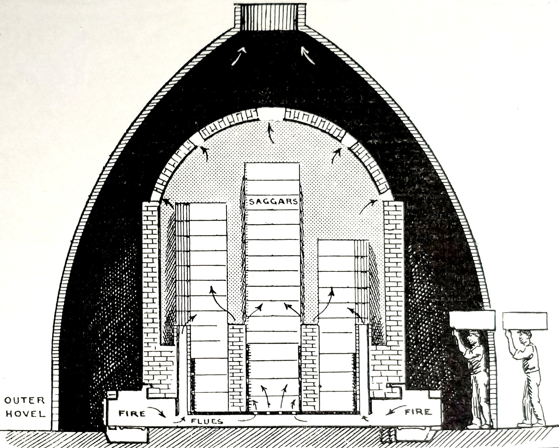
The main feature of this type of bottle oven is that the freestanding hovel is completely separate from the freestanding firing chamber standing within it. The gap between the two is sufficient to create a working space for the fireman and his oven men. The width of that space could be as narrow as a wheel barrow but was usually somewhat wider to allow the ovenmen to wield a shovel when lumping and baiting the oven. It also needed to be wide enough to allow the fireman to use a poker or a trials rod - the long rod with a hooked end used to extract firing trials from deep inside the firing chamber during firing.
MORE DETAIL : This bottle oven consists of an inner firing chamber in which the pottery was placed and fired. The firing chamber had a domed roof called the crown. Iron bands, called bonts, were secured to the outside of firing chamber to support the brickwork during firing when it was subjected to severe mechanical stress caused by temperature rise and fall.
The firing chamber is enclosed by a bottle shaped structure called the hovel. By law the hovel was required to be at least 60 feet tall. The hovel acts as a chimney, taking away the smoke and products of combustion. It also creates draught for the fires and protects the inside from the weather. The hovel also encloses the work space used by placers, ovenmen, odd men and the fireman. Sometimes the hovel was adjacent and built together with the factory workshops.
Entry to the inside of the firing chamber is through a doorway called the wicket. This doorway is tall enough for a placer with a full saggar balanced on his head to pass through easily. During firing the wicket was sealed with layered bricks, daubed over with clay and silica sand. It is then known as the clammins.
Firemouths, situated around the outside of the firing chamber at ground level, are connected to brick flues and bags (small chimneys) on the inside. These carry the intense heat from the burning coal to the pottery inside. The flues converge at the well hole at centre of the domed floor of the chamber.
Heat rises up through the setting (containing the pottery in saggars) and then out through the top of the firing chamber and up through the chimney.
When used to fire biscuit earthenware a bottle oven would reach temperatures of over 1200ºC.
The updraught stack oven has no separate hovel. This is the form developed when a series or row of ovens were grouped together in a workshop, the chimneys rising through the roof of the building.
These ovens were solid and compact but they tended to be difficult to repair since the chimney rose directly from the crown. (What does the owner do if a fault appears in the structure of the firing chamber? He might have had to knock the whole lot down and start all over.) These ovens also took longer to cool.
The updraught skeleton oven looks very similar to the updraught stack oven but it was easier to maintain. See below.
In an updraught skeleton oven the chimney is built up from ground level, very close to but completely separate from, the firing chamber. The gap between the two structures is about the width of a building brick. The freestanding firing chamber could be maintained, or even demolished and rebuilt, leaving the hovel chimney untouched.
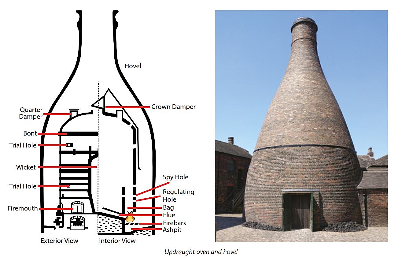 |
| Updraught hovel oven. Cross section and external view of an oven at Gladstone Pottery Museum, Longton. The gap between the hovel and firing chamber was sufficiently wide to give the fireman and his ovenmen enough space to work. Drawing and photo: Terry Woolliscroft Collection |
MORE DETAIL : This bottle oven consists of an inner firing chamber in which the pottery was placed and fired. The firing chamber had a domed roof called the crown. Iron bands, called bonts, were secured to the outside of firing chamber to support the brickwork during firing when it was subjected to severe mechanical stress caused by temperature rise and fall.
The firing chamber is enclosed by a bottle shaped structure called the hovel. By law the hovel was required to be at least 60 feet tall. The hovel acts as a chimney, taking away the smoke and products of combustion. It also creates draught for the fires and protects the inside from the weather. The hovel also encloses the work space used by placers, ovenmen, odd men and the fireman. Sometimes the hovel was adjacent and built together with the factory workshops.
Entry to the inside of the firing chamber is through a doorway called the wicket. This doorway is tall enough for a placer with a full saggar balanced on his head to pass through easily. During firing the wicket was sealed with layered bricks, daubed over with clay and silica sand. It is then known as the clammins.
Firemouths, situated around the outside of the firing chamber at ground level, are connected to brick flues and bags (small chimneys) on the inside. These carry the intense heat from the burning coal to the pottery inside. The flues converge at the well hole at centre of the domed floor of the chamber.
Heat rises up through the setting (containing the pottery in saggars) and then out through the top of the firing chamber and up through the chimney.
When used to fire biscuit earthenware a bottle oven would reach temperatures of over 1200ºC.
1.2 Updraught stack (close-coupled) oven
This type of bottle oven has its chimney built directly onto the shoulder of the crown of the oven. This design was sometimes known as 'close-coupled'.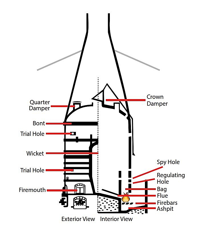 |
| Updraught stack oven. Cross section. The chimney was built directly onto the shoulder of the crown of the oven Drawing: Terry Woolliscroft Collection |
The updraught stack oven has no separate hovel. This is the form developed when a series or row of ovens were grouped together in a workshop, the chimneys rising through the roof of the building.
These ovens were solid and compact but they tended to be difficult to repair since the chimney rose directly from the crown. (What does the owner do if a fault appears in the structure of the firing chamber? He might have had to knock the whole lot down and start all over.) These ovens also took longer to cool.
The updraught skeleton oven looks very similar to the updraught stack oven but it was easier to maintain. See below.
 |
| Updraught stack oven. Bottle oven chimneys rising through the roof of the factory the former J T Fell's Anchor Works in Sutherland Road, Longton Photo credit: Bert Bentley Date: 1960s |
1.3 Updraught skeleton oven
At first sight this looks similar to an updraught stack oven. But it is constructed differently. The updraught skeleton oven tended to be preferred by potbank owners since it was less expensive to maintain. Work could be easily carried out on the firing chamber without affecting the hovel chimney.In an updraught skeleton oven the chimney is built up from ground level, very close to but completely separate from, the firing chamber. The gap between the two structures is about the width of a building brick. The freestanding firing chamber could be maintained, or even demolished and rebuilt, leaving the hovel chimney untouched.
 |
| Updraught skeleton oven. Note the narrow gap (about a brick's width) between the firing chamber and the hovel chimney. Drawing: Terry Woolliscroft Collection 2019 |
In order to allow the fireman and his ovenmen to attend to the firemouths in the firing chamber large gaps needed to be created in the brickwork around the base of the chimney. The diagram below shows how open arches were built into the chimney. The design and shape of these arches varied. One of the arches led to the clammins.
 |
| Stylised construction of the skeleton chimney. The entire chimney was supported on 'legs' The open, arched, spaces in the chimney allowed the fireman and his ovenmen to tend to the firemouths in the firing chamber. Drawing: Terry Woolliscroft Collection, 2019 |
 |
| Construction of the skeleton chimney. Details of the open arches with the firing chamber beyond. Drawing: Andy Perkin, Potteries Heritage Society, 2019 |
 |
| Skeleton bottle oven at Phoenix Works, Longton The firing chamber is built separately from its surrounding skeleton chimney. You can see the gap between the two here, by the wicket. |
This variant, just as the updraught stack oven, could be built in a row in a workshop, the chimneys rising through the roof.
This design of oven became very popular in the early 1900s because it seemed to combine all the best qualities of all the different types of updraught oven. It was simple in design and construction, relatively simple to operate, easy to build and repair and gave satisfactory results.
Since this design allowed the safe demolition and complete removal of the firing chamber some pottery owners had the firing chamber removed to create work or storage space. A few still standing in the Potteries are known as 'hovel only' for this reason. There is a fine example at Heron Cross Pottery.
This method of baiting was regarded as 'old fashioned' by some but it did have the distinct advantage that cold air was prevented from rushing into the firing chamber flues (unlike a firemouth with opening front doors which did allow cold air to be sucked into the interior).
A hob-mouthed oven could be an updraught stack type, or an updraught skeleton type. Two good examples, which still stand, (2023) are in Stoke at the Falcon Pottery, Sturgess Street. The remains of a hob-mouthed oven can also be seen at the Spode factory, in Stoke.

Technically, the oven should be called 'updraught-downdraught' since the hot gasses pass through the setting of saggars not once but twice, theoretically extracting as much heat as possible from the burning coal.
From the firemouths, the intensely hot gases flow upwards to the crown where they are deflected downwards through the setting of saggars containing pottery, and are then drawn out through the flues in the floor of the oven. The control of the flow of the hot gases was made by the use of dampers (robust adjustable flaps, over the crown, quarter and shoulder holes) which were opened and closed during the firing cycle. It was skilled work. Unfortunately the process has never been recorded, not even written down.
Downdraught ovens were used mainly for biscuit firing, as it was considered that they were more economical in fuel, and that they could be worked to produce a more regular heat over all the oven.
There are three variants of the downdraught oven:

There are three types of muffle kiln:
A muffle kiln was a lot smaller than the other types of bottle oven and temperatures reached were lower at around 850ºC. This temperature made the decorated colours permanent (without firing, the colours would easily rub or wash off) and did not need the higher temperatures required biscuit and glost.
This design of oven became very popular in the early 1900s because it seemed to combine all the best qualities of all the different types of updraught oven. It was simple in design and construction, relatively simple to operate, easy to build and repair and gave satisfactory results.
Since this design allowed the safe demolition and complete removal of the firing chamber some pottery owners had the firing chamber removed to create work or storage space. A few still standing in the Potteries are known as 'hovel only' for this reason. There is a fine example at Heron Cross Pottery.
1.4 Updraught hob-mouthed oven
This bottle oven had an older design of firing chamber, largely superseded in the late 19th and early 20th centuries. The firemouths of these ovens were built out by up to 2 feet from the firing chamber side walls to create a hob or shelf above them. Coal was shovelled though a square feed-hole in the hob and down onto the firebed below. The hole was covered, when baiting had finished, by a slab of fireclay. |
| Fireman attending the hob-mouth of a bottle oven at Middleport Pottery Photo: Courtesy Donald Morris Collection Date: 1965 |
 |
| Updraught hob mouthed bottle oven View of baiting through the top of the hob Photo: unknown source Date: unknown |
This method of baiting was regarded as 'old fashioned' by some but it did have the distinct advantage that cold air was prevented from rushing into the firing chamber flues (unlike a firemouth with opening front doors which did allow cold air to be sucked into the interior).
A hob-mouthed oven could be an updraught stack type, or an updraught skeleton type. Two good examples, which still stand, (2023) are in Stoke at the Falcon Pottery, Sturgess Street. The remains of a hob-mouthed oven can also be seen at the Spode factory, in Stoke.
 |
| Updraught hob-mouthed bottle ovens. Falcon Works, Sturgess Street, Stoke Photo: unknown source Date: unknown |
 |
| The hob mouth Falcon Works, Sturgess Street, Stoke Photos: Terry Woolliscroft Collection Date: May 1976 Photo taken during The Bottle Oven Survey 1976 here> |
 |
| Baiting the hob-mouthed oven Photos: unknown source Date: unknown |
 |
| Baiting the hob-mouthed skeleton oven Fieldings, Crown Devon Pottery, Stoke Photo courtesy: The Sphere Magazine Date: 1930 |
SUMMARY - updraught bottle ovens
The graphic shows the differences between stack, skeleton and hovel ovens.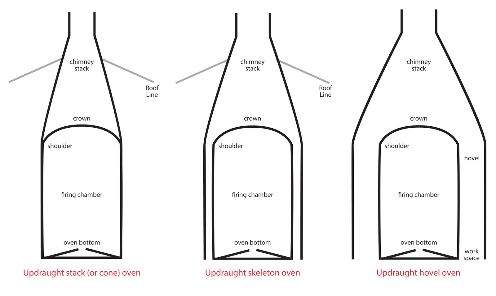
2) POTTERS' DOWNDRAUGHT BOTTLE OVEN
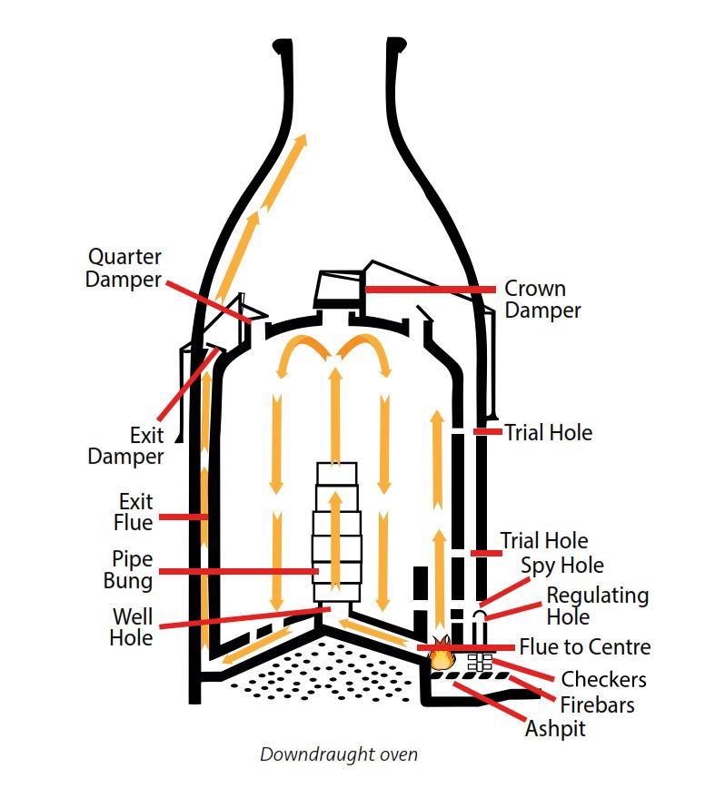
This type of bottle oven has a much more complex design than the simple updraught. It was developed in the late 1800s and early 1900s to make more efficient use of the fuel - coal.Technically, the oven should be called 'updraught-downdraught' since the hot gasses pass through the setting of saggars not once but twice, theoretically extracting as much heat as possible from the burning coal.
From the firemouths, the intensely hot gases flow upwards to the crown where they are deflected downwards through the setting of saggars containing pottery, and are then drawn out through the flues in the floor of the oven. The control of the flow of the hot gases was made by the use of dampers (robust adjustable flaps, over the crown, quarter and shoulder holes) which were opened and closed during the firing cycle. It was skilled work. Unfortunately the process has never been recorded, not even written down.
Downdraught ovens were used mainly for biscuit firing, as it was considered that they were more economical in fuel, and that they could be worked to produce a more regular heat over all the oven.
There are three variants of the downdraught oven:
- Downdraught within a hovel
- Downdraught with separate chimney - Clement Robey Patent
- Downdraught with integral chimney - Wilkinson Patent
2.1 Downdraught within a hovel
The drawing below shows a downdraught bottle oven, with a separate hovel. The hovel acts as the chimney to create a draught while the oven is firing. It also protected the oven itself, and the placers and firemen employed to make it work. The width of the gap between the hovel and the firing chamber was sufficiently wide for the ovenmen to use a wheel barrow, for baiting and for drawing trials.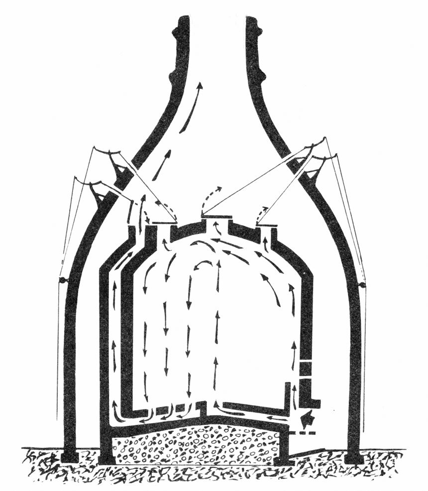
2.2 Downdraught with separate chimney - Clement Robey type
Some downdraught ovens were constructed with a receiving well or chamber underneath the firing chamber floor into which the downdraught flues ran. From this chamber a main flue was connected to a tall chimney standing separately from the oven. This chimney could be connected and used in common by two or more downdraught ovens. The main flue to this chimney was fitted with an iron regulator door that was opened or closed to control the draught. The oven was bottle-shaped similar to an updraught bottle oven.
Two examples of this type of bottle oven remain standing at Phoenix Works, King Street, Longton, Stoke-on-Trent. Details here >
 |
| Bottle oven - downdraught skeleton oven, with separate chimney. Clement Robey type as found at Phoenix Works, Longton. Path of hot gasses shown in yellow. Drawing: by Andy Perkin of Potteries Heritage Society based on an original by Terry Woolliscroft Date: Aug 2021 |
The two downdraught bottle ovens which remain standing at the Phoenix Works, Longton, are of the Clement Robey Patent. They are linked by a separate tall chimney. The general layout of the ovens at Phoenix Works is shown in the following diagram.
 |
| Downdraught bottle ovens sharing tall chimney Path of hot gasses shown in yellow Drawing: Terry Woolliscroft Collection Date: March 2021 |
This type of oven was lumped, kindled (lit), and baited in the same way as an updraught oven, but as the temperature rose the crown hole was closed and the regulator door in the flue to the outside chimney was opened. Heat was thus drawn, by draught, from the firemouths and up through the bags to the crown. It was then deflected down through the setting of saggars containing pottery, into the bottom of the oven, into the exit or extract flues, and then away to the outside chimney.
The "Clement Robey's Patent Oven" is a downdraught oven with separate chimney. The patent also included the method for converting an existing updraught oven to a downdraught.
"Patented by Clement Robey, of Sunnybank, in the Parish of Wolstanton, in the County of Stafford, General Agent; Edward Banks; and Thomas Forester, both of Hanley," British Patent No.970
Sealed the 26th August 1873, and dated the 15th March 1873.
Signed by Thomas Forester
Clement Robey was not the inventor of the new downdraught kiln but the agent who acted on behalf of Edward Banks and Thomas Forester.
Link to Robey's Patent: https://books.google.co.uk/books?id=o-VOAQAAMAAJ&vq=970&pg=RA18-PP1#v=onepage&q&f=false
It was claimed that this new oven design would save 35 to 50% in fuel, would produce a more uniform finished product, and would reduce saggar losses. The flat floor to the oven helped during placing. Sampson Bridgwood Ltd. of Longton invested in Robey ovens in 1880 but by 1890 described the alterations as a 'failure'. The oven was difficult to use.
 |
| Advert for Robey's Patent Downdraught Oven Source: Keates Directory of the Potteries and Newcastle 1879 |
There was a great deal of interest amongst Staffordshire potters in the 1880s for improving the performance of pottery ovens. Wilkinson and Minton also took out oven improvement patents. More here>
2.3 Downdraught with integral chimney -Wilkinson type
"Wilkinson Patent" downdraught ovens were constructed with separate exit flues below the oven base, rather than with a receiving chamber as described above in the Robey Patent. This Wilkinson type oven avoided the expense of the separate outside chimney. The exit flues continued up the inside walls of the oven, between the bags, eventually connecting to the oven's integral bottle-shaped chimney above the crown. They were sometimes known as a "true downdraught."
A J WILKINSON DOWNDRAUGHT OVEN
Ovens for Firing Pottery
A J Wilkinson, Burslem
English Patent 4356, March 20th 1890
Type of bottle oven. Downdraught.
 |
| English Patent No. 4356 March 20th 1890 Improvements in Ovens for Firing Pottery A.J. Wilkinson, Burslem |
Three examples of this type of downdraught still exist (2023) in the Potteries at Bournes Bank in Burslem. Wilkinson's home town.
After lumping, kindling, and first baiting, when the oven temperature was beginning to rise, hot gases passed from the firemouths, into the bags and up to the crown. Here the hot gases were deflected downwards through the setting (between the saggars containing pottery) and down through the flues in the oven floor. The hot gases then passed to the vertical flues in the inside walls to escape above the crown and up into the bottle-shaped chimney.
 |
| Downdraught bottle oven with integral chimney. Wilkinson Patent. The path of the hot gases from the firemouths was controlled by the use of dampers. Drawing: Terry Woolliscroft Collection |
The construction of this type of oven was complex and expensive. Here is a rare architect's drawing of a bottle oven. Most were built without any plans at all.
 |
| Downdraught bottle oven with integral chimney. Wilkinson Type. Extract from a drawing by Stanley Hind Date: 1937 Larger file for download here> |
Description in 2.1 and 2.2 above are edited extracts from Chapter 13, Ovens and their Construction, from The Manufacture of Earthenware by Ernest Albert Sandeman, published 1921.

The oven has:
Click here> for a ten-frame Gif of the Bottle Oven Model on a turntable
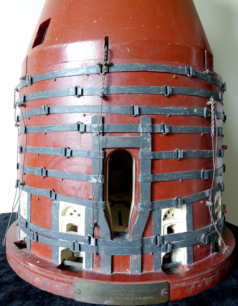
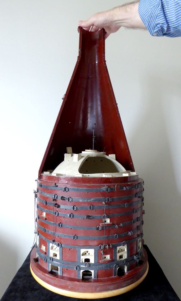
MODEL OF A WILKINSON DOWNDRAUGHT BOTTLE OVEN, WITH INTEGRAL CHIMNEY
The photographs below show a unique model of a 'Wilkinson Patent Type' downdraught bottle oven. It was donated to Gladstone Pottery Museum> in 1977 by Howletts, the renowned Potteries bottle oven builders. The model is built to scale, exactly to the drawing above. |
| Gladstone Pottery Museum model Downdraught, Wilkinson Patent, bottle oven by Howlett 1977 |

The oven has:
- 11 x firemouths
- 1 x crown damper
- 7 x quarter dampers
- 11 x updraught flues, situated between bags
 |
| Gladstone Pottery Museum model Downdraught bottle oven by Howlett 1977 Showing the wicket, firemouths, and bonts |
 |
| Gladstone Pottery Museum model Downdraught bottle oven by Howlett 1977 Shows size of the model with viewing panel removed, showing the crown of the oven. |
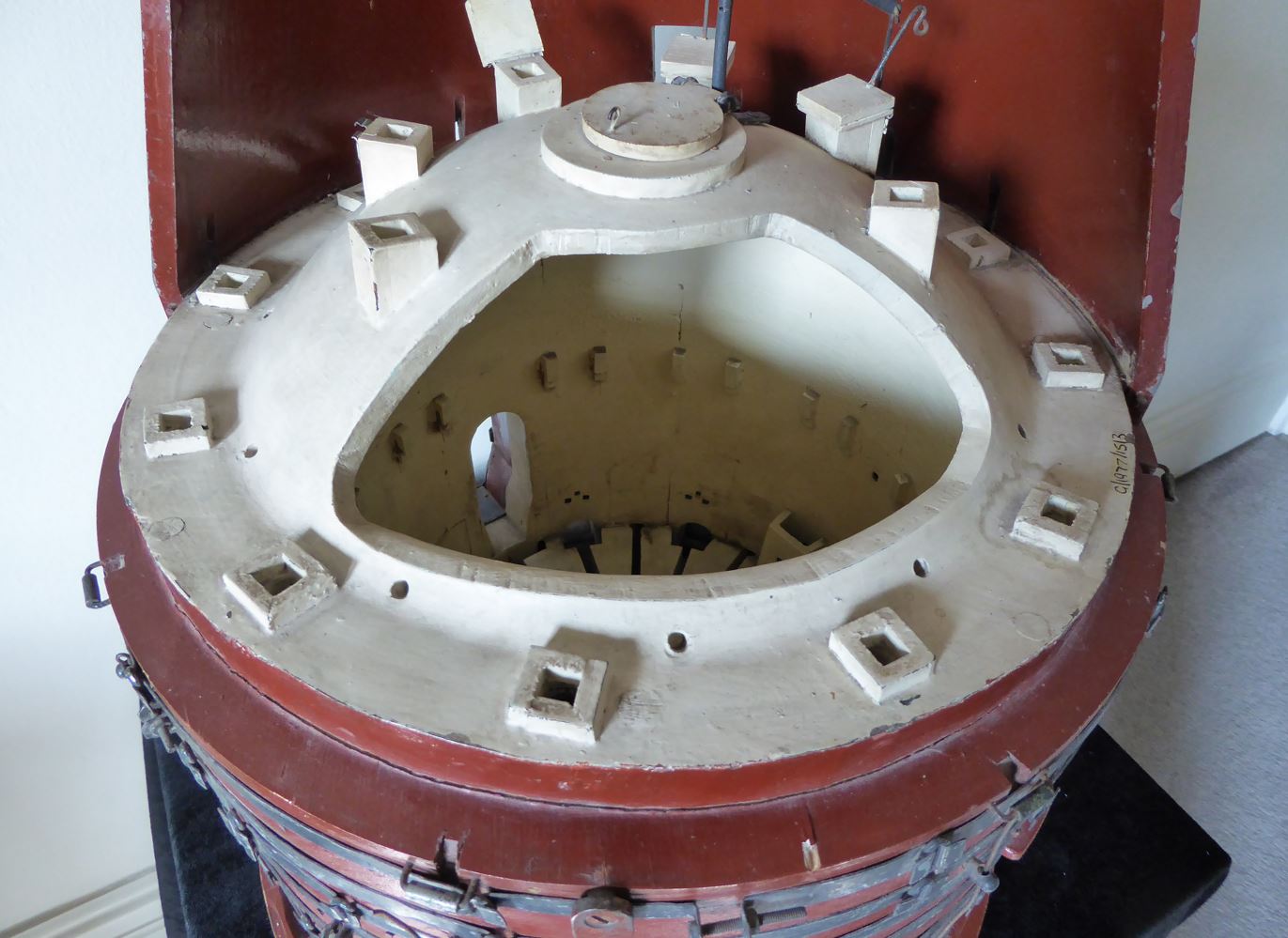 |
| Gladstone Pottery Museum model Downdraught bottle oven by Howlett 1977 Shows the top of the crown, with crown damper, quarter dampers, and flues |
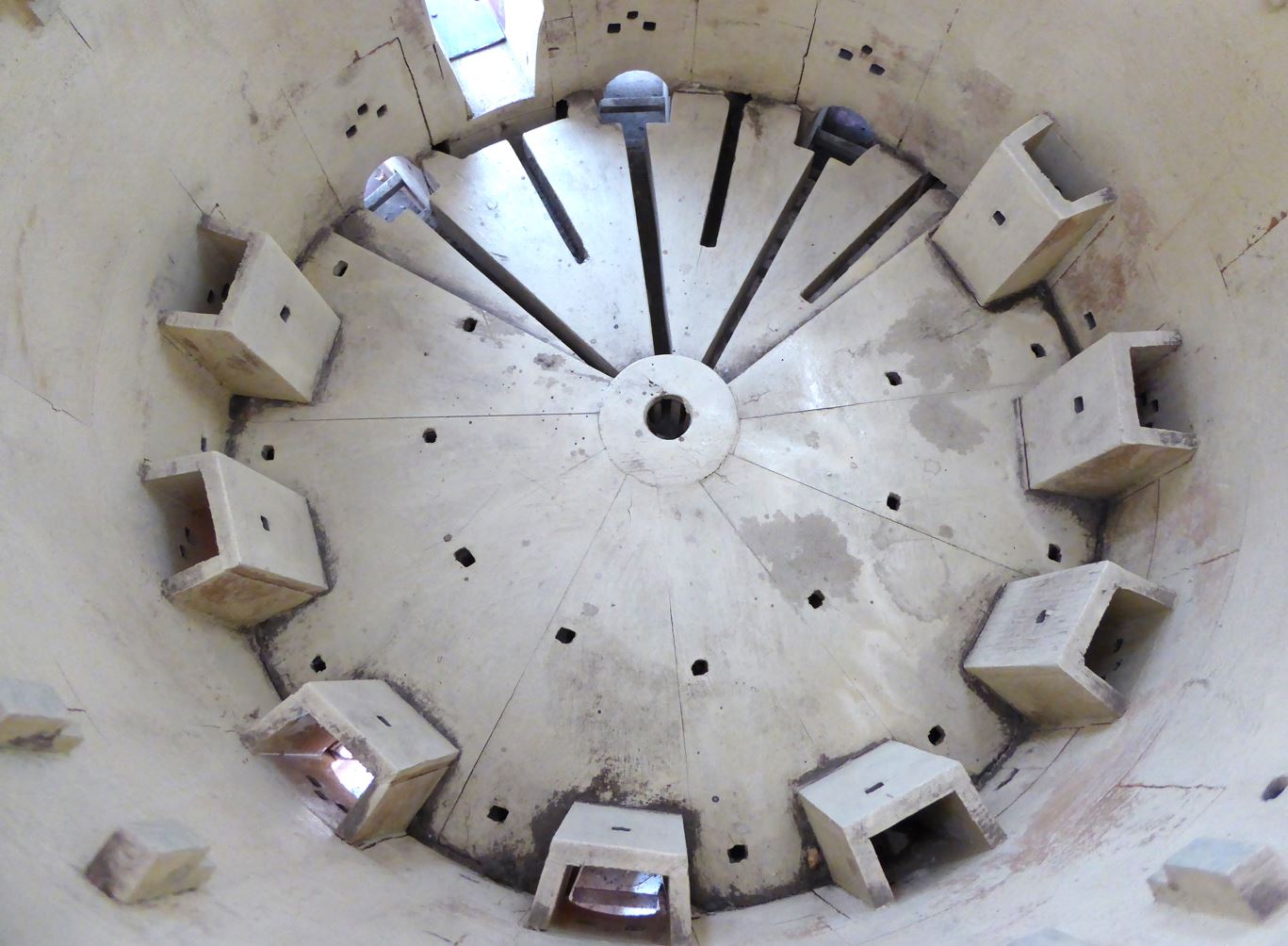 |
| Gladstone Pottery Museum model Downdraught bottle oven by Howlett built 1977 Looking down into the oven through the crown. Shows bags, well hole, and under-floor flues. |
Click here> for a ten-frame Gif of the Bottle Oven Model on a turntable
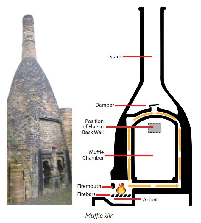
3) MUFFLE KILN
In this coal-fired bottle kiln, the flames, hot gasses and products of combustion did not directly enter the firing chamber, as in downdraught and updraught ovens, but were led around the outside of the chamber by a series of flues. In this way no saggars were required but the delicate decorated colours of the decorated pottery were still protected. The firemouths were kept separate from the kiln chamber, sometimes outside in the open air.
A muffle kiln was a lot smaller than the other types of bottle oven and temperatures reached were lower at around 850ºC.
- Decorating enamel muffle (sometimes just known as enamel muffle)
- plus one unique variant with four firing chambers
- Hardening-on muffle kiln
- Fireclay muffle kiln
3.1 Decorating enamel muffle kiln
This type was used for the decorating enamel firing and built, as in other muffle kilns, in such a way that the flames and harmful gases of combustion were kept away from the pottery in the setting.A muffle kiln was a lot smaller than the other types of bottle oven and temperatures reached were lower at around 850ºC. This temperature made the decorated colours permanent (without firing, the colours would easily rub or wash off) and did not need the higher temperatures required biscuit and glost.
 |
| Muffle kiln, for firing decorated pottery External view and cross section of the unique kiln at Gladstone Pottery Museum, Longton Drawing and photo: Terry Woolliscroft Collection |
 |
| On the left: inside the muffle kiln chamber, on display at Gladstone Pottery Museum 2014 On the right: the exterior of a muffle kiln showing four firemouths. Market St., Longton. Photo: unknown source Date: Unknown |
 |
| Muffle decorating or enamel kiln Huge, five-mouthed kiln. Fireman baiting. Possibly Wedgwood, Etruria Photo: unknown source Date: unknown |
| Muffle kiln, Furnivals, Elder Road, Cobridge Charlie Boardman emptying the ash pit after a firing. Photo: Courtesy of Jenny Ward Date: 1930s |
 |
| Muffle kiln cross section |
A unique variant
One unique variant of the decorating muffle kiln still exists in Stoke-on-Trent. It was built sometime between 1924 and 1930 and is the only surviving 4-chambered, double-deck (2 up, 2 down) muffle kiln. It stands in Burslem at what is now the Moorlands Pottery, in Moorland Road.
In a deed dated 1st January 1930, it was described as "a pair of four-mouth, double-deck kilns which had originally been designed for firing tiles, and the lessor (Doulton) agreed to alter both bottom kilns to make them suitable for enamel firing."
 |
| Double deck decorating muffle kiln Moorland Pottery, Moorland Road, Burslem Photo: By courtesy of Phil Crow ABIPP ARPS Date: May 2023 |
The kiln may have been originally entirely enclosed (except for the chimney stack) in a workshop.

Drawing: Andy Perkin, Potteries Heritage Society, 2023
The drawing clearly shows the four individual firing chambers and the path of the flow of the combustion gases. The flue in the back wall is about the size of a building brick (see photo below) and may have been used as a spy hole, trials holes or regulator hole in each chamber.
Extract from an article about Enamel and Hardening-on Kilns 1927
download pdf here>
Photos here> show the construction of a huge muffle kiln, for firing fireclay sinks, baths and urinals at the Twyfords factory, Shelton New Road, Cliffe Vale, Stoke-on-Trent.
When they are in their raw state, flint pebbles and ox bones are impossible to crush as they are far too hard and tough. Calcination changes the nature of these materials to such an extent as to make them suitable for easy crushing and then milling to a fine powder.
Calcining kilns for either flint or bone were similar in construction. The kiln could consist of one or two firing chambers. If the kiln had two chambers, side by side, a single chimney served both.
FLINT CALCINING
Flint is a major constituent of pottery bodies such as earthenware, sanitary earthenware, and wall tiles. Flint is a refractory material used to provide silica in the body. It is also used in glazes. It increases firing temperature and craze resistance but reduces plasticity and shrinkage. In 1950 around 2000 tons of flint were calcined weekly in the Potteries to meet the requirements of the industry.
Flint occurs naturally as hard, black/grey pebbles within cretaceous chalk beds. When calcined above 1000ºC, crystalline water is driven off, shattering the pebbles and leaving them softer, lighter and whiter.
Filling the calcining kiln was a skilled job. The bowl of the kiln was filled with the flint pebbles, layering it with fuel. Alternate layers of flint (between 5 and 6 tons in total) and coal, usually slack, (about 12 cwts - 610 kgs) ) were charged into the funnel-shaped firing chamber. The charge rested on 2.5 cwts (127 kgs) of lump coal in the grate at the bottom of the chamber. This was then ignited with paraffin and the kiln allowed to burn itself out without further attention.
The time taken to calcine flint would depend on the type of flint, the quality of the fuel and the climatic conditions, but would take 8 to 16 hours. Bone (see below) would be quicker.
The calcined charge was emptied from the base of the chamber, screened to separate the ash, or simply "forked".
ANIMAL BONE CALCINING
Bone is a component of a particular type of pottery which is known as Bone China. Calcined animal bone, usually cattle bones, preferably the shin bones of oxen, (honestly!) are used.
The Spode company, under Spode I and Spode II, is credited with having perfected the bone china formula before 1800. 1799 is the most likely date but it could perhaps be even a little earlier from circumstantial evidence. https://spodehistory.blogspot.com/p/bone-china.html
About 50% of the bone china recipe consists of calcined ox bone. The remaining 50% being made up of China Clay and Cornish Stone. It is the bone which gives bone china its brilliant whiteness, strength and translucency.

Bones are calcined at about 1150ºC to ensure all animal matter and other contaminants are burned away to render the calcium phosphate inert. Bone could be calcined with coal or wood, although wood was preferred in order to reduce the possibility of iron, found in coal, contaminating the batch. Bones would be layered with the fuel, as in flint calcination. Because of its organic nature bone required little fuel once combustion had started.
After calcination, bone ash can be ground to a fine powder and added to the bone china body.
It is recorded that in 1838 bones were being purchased for use in a pottery company's bone china formula at a cost of "£6 per ton." The company said that they could take "one ton a fortnight" and insisted with the supplier that the bones should "be unboil'd fresh meat bones, no horse bones." The company insisted that "boiled bones were no use at all."
OTHER TYPES
Other types of kiln included frit and lime kilns which were used by material suppliers.
%20TWs%20s.jpg) |
| 'Flue' in rear wall of each firing chamber Moorland Pottery, Moorland Road, Burslem Photo: Terry Woolliscroft Collection Date: 2019 |
3.2 Hardening-on muffle kiln
Biscuit ware which had been decorated with an underglaze print or with hand painted pattern needed to be 'hardened on' so that the decoration didn't smudge during glaze dipping. The hardening-on muffle kiln was usually smaller than an decorating muffle kiln, and fired at a relatively low temperature of around 700ºC. |
| Hardening-on muffle kiln - interior. Spode factory, Stoke Photo: source unknown Date: 1900 - 1920 |
Extract from an article about Enamel and Hardening-on Kilns 1927
3.3 Fireclay muffle kiln
Fireclay products, baths and sinks for use in bathrooms and kitchens, are very large and heavy! A fireclay bath for instance needed to be hauled around the factory by a team of at least four men with trolleys, ropes and pulleys. These huge pottery products could not, therefore, be fired in a conventional bottle oven using saggars to protect them - no saggar was big enough! So fireclay was fired in a muffle kiln. Here the product was stacked in a huge box-like chamber which was sealed away from the flames and products of combustion. |
| Muffle kiln firemouths Twyfords, Stoke fireclay factory Date: 1929 |
Photos here> show the construction of a huge muffle kiln, for firing fireclay sinks, baths and urinals at the Twyfords factory, Shelton New Road, Cliffe Vale, Stoke-on-Trent.
4) CALCINING KILN
A calcining kiln was not used for firing pottery pieces but for burning or 'roasting' flint pebbles or animal bones to make them relatively soft and friable before they were crushed and ground for inclusion in the pottery body recipe. The kiln fired the materials to very high temperature (above 1000ºC) to make them easily crushed to a fine powder.When they are in their raw state, flint pebbles and ox bones are impossible to crush as they are far too hard and tough. Calcination changes the nature of these materials to such an extent as to make them suitable for easy crushing and then milling to a fine powder.
Calcining kilns for either flint or bone were similar in construction. The kiln could consist of one or two firing chambers. If the kiln had two chambers, side by side, a single chimney served both.
 |
| Flint calcining kiln - cross section Drawing and Photo: Terry Woolliscroft Collection |
FLINT CALCINING
Flint is a major constituent of pottery bodies such as earthenware, sanitary earthenware, and wall tiles. Flint is a refractory material used to provide silica in the body. It is also used in glazes. It increases firing temperature and craze resistance but reduces plasticity and shrinkage. In 1950 around 2000 tons of flint were calcined weekly in the Potteries to meet the requirements of the industry.
 |
| Raw (uncalcined) flint pebbles - each about 4" diameter Photo: Terry Woolliscroft Collection Date: 1980 |
Flint occurs naturally as hard, black/grey pebbles within cretaceous chalk beds. When calcined above 1000ºC, crystalline water is driven off, shattering the pebbles and leaving them softer, lighter and whiter.
Filling the calcining kiln was a skilled job. The bowl of the kiln was filled with the flint pebbles, layering it with fuel. Alternate layers of flint (between 5 and 6 tons in total) and coal, usually slack, (about 12 cwts - 610 kgs) ) were charged into the funnel-shaped firing chamber. The charge rested on 2.5 cwts (127 kgs) of lump coal in the grate at the bottom of the chamber. This was then ignited with paraffin and the kiln allowed to burn itself out without further attention.
 |
| Flint calcining kiln Still standing (2019) in Hanley. Former Johnson Bros., Trent Works. Kiln is charged and ready for firing to calcine flint pebbles Terry Woolliscroft Collection Date: July 1975 |
The time taken to calcine flint would depend on the type of flint, the quality of the fuel and the climatic conditions, but would take 8 to 16 hours. Bone (see below) would be quicker.
The calcined charge was emptied from the base of the chamber, screened to separate the ash, or simply "forked".
 |
| Flint calcining kilns Furlong Mills, Burslem Photo courtesy: Andy Perkin, Potteries Heritage Society Still standing in 2022. Photo date: July 2019 |
 |
| Flint calcining kilns - no longer standing Unknown location Photo: source unknown Date: unknown |
 |
| Flint calcining kiln, two firing chambers Middleport Mill, Milvale Steet, Middleport Still standing 2022 Photo: Terry Woolliscroft Collection Date: Feb 2022 |
Bone is a component of a particular type of pottery which is known as Bone China. Calcined animal bone, usually cattle bones, preferably the shin bones of oxen, (honestly!) are used.
 |
| Cattle bones, from the butcher, unboiled Awaiting calcining be for use in Bone China Possibly Minton Date: c1900 |
The Spode company, under Spode I and Spode II, is credited with having perfected the bone china formula before 1800. 1799 is the most likely date but it could perhaps be even a little earlier from circumstantial evidence. https://spodehistory.blogspot.com/p/bone-china.html
About 50% of the bone china recipe consists of calcined ox bone. The remaining 50% being made up of China Clay and Cornish Stone. It is the bone which gives bone china its brilliant whiteness, strength and translucency.

Bones are calcined at about 1150ºC to ensure all animal matter and other contaminants are burned away to render the calcium phosphate inert. Bone could be calcined with coal or wood, although wood was preferred in order to reduce the possibility of iron, found in coal, contaminating the batch. Bones would be layered with the fuel, as in flint calcination. Because of its organic nature bone required little fuel once combustion had started.
After calcination, bone ash can be ground to a fine powder and added to the bone china body.
 |
| Calcining kiln Dalehall Mills Ltd., Adkins Street, Cobridge, Stoke-on-Trent Photo: D. Morris Date: c1975 Now demolished. Courtesy of Staffordshire Past Track here> |
It is recorded that in 1838 bones were being purchased for use in a pottery company's bone china formula at a cost of "£6 per ton." The company said that they could take "one ton a fortnight" and insisted with the supplier that the bones should "be unboil'd fresh meat bones, no horse bones." The company insisted that "boiled bones were no use at all."
OTHER TYPES
Other types of kiln included frit and lime kilns which were used by material suppliers.
5) DOWNDRAUGHT BEEHIVE KILN, with separate tall chimney
This is not a bottle oven or bottle kiln since it has no characteristic bottle-shaped chimney. But it is included here since it could be found, at one time, in large numbers in the landscape of the Potteries. Today, none of them remain. Just a few can be found in other parts of the UK..jpg) |
| Hartshill Beehive kilns - Caddick Tiles 1960s |
Some downdraught kilns were used for the firing of bricks, tiles, drainpipes, and chimney pots. Some were used to fire large domestic pottery and salt glazed pottery. One true downdraught beehive kiln still exists (2020) and is still fired with coal and salt at Bardon Mill, Northumberland. Details here>.
The kiln, usually free standing and sometimes outside, exposed to all weathers, had a domed roof and a perforated floor under which ran exit flues leading to the separate chimney. Coal was kindled (lit) and burned fiercely inside the firemouths around the outside of the oven. Hot gases were directed upward from mouths through bags (small chimneys inside the kiln itself) and then downwards from the underside of the crown (domed roof) through the setting and into the under-floor flues, pulled by the draught from the separate chimney.
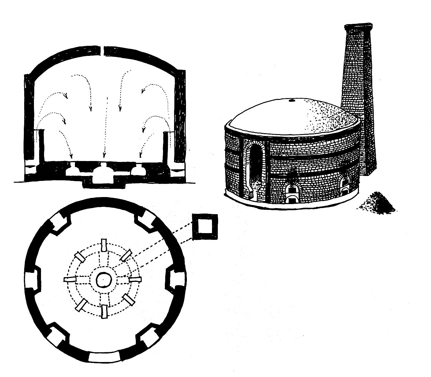 |
| Round downdraught kiln also known as a 'beehive kiln' |
 |
| Cross section of a beehive downdraught kiln Image: source unknown |
The downdraught beehive kiln would have a capacity of about 12,000 bricks, and up to 30,000 floor tiles.
The firing cycle took around two weeks: two days for setting (stacking and filling), three days for the water smoking period to drive off any moisture left in the bricks or tiles, two days for firing to full temperature, one day soak at full heat, then another three or four days to cool down and a further day to draw (empty).
 |
| Wheatly & Co Ltd, Trent Vale, Stoke-on-Trent Photo: source unknown Date: mid 1950s |
 |
| Beehive brick and floor tile kiln Wheatly & Co Ltd, Trent Vale, Stoke-on-Trent Photo: source unknown Date: mid 1950s |
 |
| Beehive brick and floor tile kiln A worker on top of the kiln in the yard of Wheatly Brick & Tile Co. Photo: source unknown Date: mid 1950s |
 |
| Beehive brick and floor tile kiln Wheatly & Co Ltd, Trent Vale, Stoke-on-Trent Baiting the hob-mouthed kiln with coal Photo: Source unknown Date: mid 1950s |
 |
| Beehive brick and floor tile kilns. At least 22 of them can be seen here Knutton Tileries Photo: source unknown Date: 1930s |
 |
| Fireclay Hole and Works, Cobridge, Stoke-on-Trent Photo: Source unknown Date: unknown |
 |
| Tunstall. Downdraught beehive kiln. Note separate chimney on right. Daniel Platt & Sons, brick & tile manufacturers. The Perry Family firing the kiln. Source: unknown Date: some time before 1935 |
 |
| Burslem Sneyd pipe works. Near the loop line railway bridge, just off Hot Lane. Source: Bert Bentley Date: 1960s |
Firing a downdraught kiln film
Hands: Clay Pipe Works, IrelandMaking and firing with coal. A fascinating & rare film on the complete production of industrial clay drainage pipes and hand made Armstrong junctions, all fired in the largest beehive kiln in Ireland at Kingscourt, Co. Cavan. Made in 1983. The full film is ½ hour long. Here is a clip starting at 14:50 showing the entire firing process. Watch the film from the beginning to see drainage pipes being made. This film is important since it shows how a beehive kiln was placed, fired, and drawn.
Description of firing a downdraught beehive kiln by Alan Hopwood, May 2016
The usual downdraught kiln was a 'beehive' shape with 10 fire mouths and a free-standing chimney, a few yards away. Then there were a series of flues going underground from the beehive to the chimney. At the bottom of the chimney was a big firehole.This type of kiln was quite devilish to get going. A good fire was made up in the chimney so as to get a good draught through the flues from the beehive itself. Then you lit the fires round the beehive but as I said before it was quite sluggish at first. All the heat in this case was collected in the dome and was then drawn down through whatever wares were being fired, through the flues and across the yard to the free standing chimney.
I wouldn't like to guess what the temperatures were in these kilns but when one looked through the spyholes the light inside was more silver or even electric blue, instead of gold to white as in an updraught kiln.